|
|
Post by andymanone on Oct 14, 2018 12:45:10 GMT
Hi guys, I´ve done yesterday a little HW-Mod. With this Mod you´re able now to get root access to the C64Mini straight thru the standard Power Micro-USB port and you won't be forced to open the C64 every time you want to get root access in the future  . Whats to do therefore?First of all I took a inexpensive CH340G Mini USB to TTL converter, like this one: 
Than I removed the USB-connector and cut off the 3 pins not used (5V, VCC,3V3) 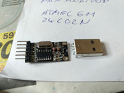  Now it´s neccessary to locate the soldering pads for RX/TX and 5V+ on your C64Mini board. TX/RX you´ll find it on inner pads ESD4/ESD5 (closed to the onboard micro-USB port), 5V+ you can grab from one of the two standard USB ports.... 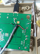 Finally you have to solder the CH304G Converter to the UART Port on your C64Mini und the RX/TX/+5V to the proper pads, thats all  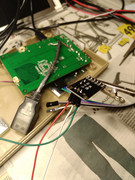  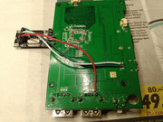
Closed C64 Mini - with successfull root access via Micro-USB port 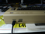 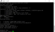 It´s not a big story, but maybe useful for someone of you  . Cheers, andY |
|
|
|
Post by ch1ller on Oct 14, 2018 14:07:01 GMT
Nice, but can u power down the mini with the Power off Button when normally connected to Power+TV or does it stay on? With my UART Adapter connected i cant do that and in your solution the CH304G is always powered as soon the mini gets turned on. I always have to take off HDMI otherwise when off but connected it disturbs my TV/ARC Connection  I wouldnt want to always unplug the Micro-USB Power Plug too |
|
|
|
Post by andymanone on Oct 14, 2018 14:19:25 GMT
Nice, but can u power down the mini with the Power off Button when normally connected to Power+TV or does it stay on? Hi ch1ller, yes it works well  ! Cheers, andY |
|
|
|
Post by deerwings on Oct 29, 2018 19:26:05 GMT
I wonder if either of those other pads near the two USB ports on the sides are linked to the same USB port, or if they're -additional- USB ports. I should do some experimenting out of curiosity.
|
|
|
|
Post by crispin on Oct 30, 2018 2:10:22 GMT
andymanone , I think you made serious mistake. Most of these UART adapters has "auto-adjust" option: when it got 5V (from Mini), it will send 5V via Tx/Rx. But Mini requires 3.3V for Tx/Rx signals - not more! Default is 5V (up to 5,5V!), not 3.3V (e.g. when you do not have "jumper switch"). It will work for some time, but this will burn something at Mini for sure, sooner or later. It depends now how much you're using it (how many data goes through, mainly to the Mini). It is old story for Arduino users: some of them, even experienced users, realized this "little problem" after few years - and usually burning 2-3 Arduinos along the way. Nasty thing is that won't stop work immediately - you don't know that you made it wrong. Look at it this way: it is like you connect 3 AA batteries at device that needs only two of them. Your fan will probably work (but faster), but many other devices won't. Usually something inside will be burnt. edit: I looked at pics once again: I really think that you have to shortcut VCC and 3V3. This is function of this jumper attached that comes with. Look at datasheets (I can send you if you can not find it). Btw, it is not CH304 but CH340 
|
|
|
|
Post by spannernick on Oct 30, 2018 10:21:59 GMT
Dam its a shame,I need a way to get round the Uart ,mine don't work,is there a place on the board I can bypass it..? This board has been out long enough now for someone to get the USB working properly maybe...  They flashed the firmware using the Power USB connector,it show them doing it in China to 8 boards at once in one of them videos.Its amazing no one has made a schematic on it.Its Identical to the CubieBoard2 development Board...See the Uart and the 2 USB ports..   See what I mean..?? it can use Uboot,Andriod and Linux images. This was made 2 years before there started work on THE64,its has the same everything, if you removed the network,sata,HP jack and that,it would be the same even has the same GPU: ARM® Mali400MP2,Complies with OpenGL ES 2.0/1.1. only thing that would be different would be the memory and the NAND thats 4 GB. for installing Android,I did say the firmware looked part Android.The development Board they used to make TheC64 Mini has the same specs as the CubieBoard2 cause it came out at the same time. CubieBoard6 is out now so its shows how old the board is TheC64 board is based on,they took over 2 years to develop the software and firmware. Oh and if the development Board they used had Ethernet then this can, its just finding were to add it to the board because it should be there somewhere on it. TheC64 Mini board is a copy of the A20-OLINUXINO-LIME development board they used,it just like Lego,parts have been moved around..  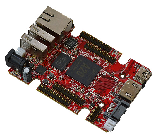 |
|
|
|
Post by andymanone on Oct 30, 2018 11:38:54 GMT
andymanone , I think you made serious mistake. Most of these UART adapters has "auto-adjust" option: when it got 5V (from Mini), it will send 5V via Tx/Rx. But Mini requires 3.3V for Tx/Rx signals - not more! Default is 5V (up to 5,5V!), not 3.3V (e.g. when you do not have "jumper switch"). It will work for some time, but this will burn something at Mini for sure, sooner or later. It depends now how much you're using it (how many data goes through, mainly to the Mini). It is old story for Arduino users: some of them, even experienced users, realized this "little problem" after few years - and usually burning 2-3 Arduinos along the way. Nasty thing is that won't stop work immediately - you don't know that you made it wrong. Look at it this way: it is like you connect 3 AA batteries at device that needs only two of them. Your fan will probably work (but faster), but many other devices won't. Usually something inside will be burnt. edit: I looked at pics once again: I really think that you have to shortcut VCC and 3V3. This is function of this jumper attached that comes with. Look at datasheets (I can send you if you can not find it). Btw, it is not CH304 but CH340  Hi crispin, Thanks for your hints. Yes, you´re right, that was a typo, it´s of course a CH340  . @3,3V: hmm not sure if it´s really sending TX/RX at 5volt level, because I guessed, w/o the jumper it will works on 3.3V level. But I will messure it asap and fix it  Cheers, andY |
|
|
|
Post by andymanone on Nov 1, 2018 22:27:57 GMT
Little update @ crispin : I can reassure you, your guess was wrong  ! I´ve just messure it with my Oscilloscope, and I´m right, it works with 3.3 volts, not 5 volts , like your afraid. So everything it´s okay with my Mod  I´m very busy at the moment, but I´ll show you the proof this weekend  Cheers, andY |
|
|
|
Post by deerwings on Nov 1, 2018 22:33:13 GMT
I purchased a similar USB-TTL adapter which was designed for Arduino for this exact same problem. This one specifies 3.3v on RX/TX. I had to disassemble the shell (was pretty easy) to get the PCB out, but this one has a slightly different pinout than anymanone's. I have mine currently soft soldered to my motherboard for now and looks like a hecken' mess, but I'm going to resolder it later more gracefully later. sayal.com/STORE/View_SPEC.asp?SKU=240984 |
|
|
|
Post by crispin on Nov 2, 2018 17:18:40 GMT
Little update @ crispin : I can reassure you, your guess was wrong  ! I´ve just messure it with my Oscilloscope, and I´m right, it works with 3.3 volts, not 5 volts , like your afraid. So everything it´s okay with my Mod  I´m very busy at the moment, but I´ll show you the proof this weekend  Cheers, andY Glad to hear it! No problem, same here: I've got two similar ones, one is sibbling of yours, both had weird oscilations if VCC is not shortwired to 3.3V. Little advice: try to measure with different power sources (e.g. phone chargers), you'll be surprised! I purchased a similar USB-TTL adapter which was designed for Arduino for this exact same problem. This one specifies 3.3v on RX/TX. I had to disassemble the shell (was pretty easy) to get the PCB out, but this one has a slightly different pinout than anymanone's. I have mine currently soft soldered to my motherboard for now and looks like a hecken' mess, but I'm going to resolder it later more gracefully later. sayal.com/STORE/View_SPEC.asp?SKU=240984Yeah, I've got two of them, 1st is CH340G like andy's, 6 pins and a jumper, 2nd is PL2303HX based and has 5 pins only. Both behave weird if VCC is not shortwired to 3.3V. If this is done, both behave OK. Still, I don't like oscilation at one, this is why I bought second one. I will make photos and measured them again, probably this weekend. This is where I bought it - hard to find it at EU, with regular price and decent time of delivery (this come very quick - less then a week): www.makershop.de/zubehoer/usb-ttl-konverter-adapter-modul-pl2303-uart-rs232-arduino-pl2303hx/www.makershop.de/module/kommunikation-module/ch340-usb/ |
|
|
|
Post by deerwings on Nov 2, 2018 17:24:29 GMT
The one I have doesn't have the 3.3 pin wired up, though it was soldered onboard, so I just soldered it with riser pins to rx/tx and then softwired the ground to the ground pin, and then soldered the USB connectors to the same places. I did actually solder the ground as well as the 5v line as well just to make sure it was grounding properly on both ends, I was receiving occasional issues that I'm not certain the cause of. The only problem I have, is that when it's powered down, I think the data pins are still keeping the UART alive so the power LED still remains on even though the unit is powered down. Same issue if I use poweroff in the console.
|
|
|
|
Post by crispin on Nov 2, 2018 17:35:55 GMT
I checked it now at makershop.de (links above):
If I remember it right from PL2303 datasheet, it should "automatically switch" - provide at Tx/Rx 3.3V or 5V, depending of power source. But, many of them just provide 5V (up to 5,6!) regardles of source - there are plenty of chinese clones that are not tested well.
Mine is not so good, but it works ok.
This is very clear. It will not provide more then 3,3V (it could be up to 3,8 in my case, depending of power source quality), but only if it is VCC+3V3 shortwired.
If you leave it open (w/o jumper), it is lottery.
Watch this:
When 3.3v isn't actually 3.3v: USB to Serial adapters
|
|
|
|
Post by deerwings on Nov 2, 2018 17:50:16 GMT
I'm not even certain the one I have is specifically a PL2303, I think it's a clone. But interestingly enough, with the way it's manufactured it's not intended to be jumpered which makes me wonder if soldering the 3.3v lead onto the 3.3v port on the board tells the unit to reference only the 3.3v instead of maybe 5v. I may have to break mine out again and measure the voltage and see where it is. I had a serial adapter that was referencing 3.8v or even up to 4v at one point, but this one was designed specifically for Arduinos. Now I'm wondering about that 3.3v wire.
|
|
|
|
Post by andymanone on Nov 3, 2018 17:41:08 GMT
Hi crispin, like promised, here my results: First of all I adjusted my oscilloscope to 0 volts (flatline): 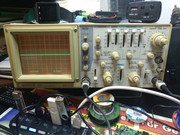 Than I took an external regulated professional Power supply and adjusted it to 3.3V (and made a crosscheck with a Voltmeter of course  ): 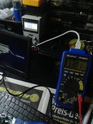 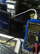 Now you can see, the oscilloscope shows the voltage change (to find now between the 90/100 lines - in the right corner you see the RPS)  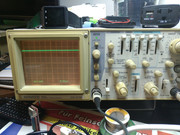 Than I messured the TX/RX lines and you can see, (it´s slightly higher) but the same result: 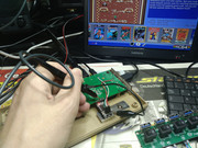 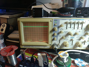 Finally a crosscheck with the external RPS on 5V: 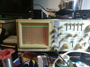 Cheers, andY |
|
|
|
Post by spannernick on Nov 4, 2018 0:40:04 GMT
Dose anyone know how I could check the RX and TX lines on TheC64 Mini...? I am guessing they have stopped working,it could be my FTD232 or CP2102...any ideas how???
|
|
|
|
Post by deerwings on Nov 4, 2018 3:15:07 GMT
Well, best way would be to remove them from the C64 Mini, and then connect the RX to the TX line and see if you get echo text to your terminal. If not, that might be the problem right there.
|
|
|
|
Post by spannernick on Nov 26, 2018 15:00:19 GMT
No its not my FTD232,I had it on 5V thats why the Uart is not working,I blown it,damn I need a new board,anyone got a spare with the Uart working..  what does TX and RX stand for ..I guess TX stands for TEXT what about RX maybe REX...  ..? So the RX line has to be 3.3V only not 5V otherwise it will blow the Uart on TheC64 Mini,well it does cos it did it to me...  |
|
|
|
Post by jj0 on Nov 26, 2018 17:57:24 GMT
No its not my FTD232,I had it on 5V thats why the Uart is not working,I blown it,damn I need a new board,anyone got a spare with the Uart working..  what does TX and RX stand for ..I guess TX stands for TEXT what about RX maybe REX...  ..? So the RX line has to be 3.3V only not 5V otherwise it will blow the Uart on TheC64 Mini,well it does cos it did it to me...  TX = Transmit RX = Receive Yeah, I have no idea what the X is for either 😉 To test your Mini's, the best I can think of is to use a multimeter and see if there's any change on the Tx if you switch the Mini on. Or maybe there's a Mini enthousiast nearby who owns an Oscilloscope? |
|
|
|
Post by deerwings on Nov 26, 2018 19:29:32 GMT
The X was essentially shorthand for 'Connection', since it sorta looks like two end points connecting in the middle.
|
|
|
|
Post by spannernick on Nov 27, 2018 22:44:28 GMT
I did put my Multimeter on the uart pins Rx and Tx on TheC64 Mini and got nothing.
|
|